Seeing the WM8750 specs, I have to agree that it would make sense to use its ADC features, and that the logical place to place an analog input would be in the remote connector.
Looking further, it looks like the WM8750 uses a 2-wire serial interface, which is pretty much synonymous with I2C. I guess that would explain the use of the i2c driver in the audio codec...
PSP remote control pinout?
that would be nice, because it is getting hard for me to visulize all these pins lol...gorim wrote:
I have a ripped-apart PSP with mainboards...maybe I should take some pics and post them.... eventually...
btw.. has anybody (other than me. the n00b who dosent know what he's doing), looked at the specs for sony's 9 pin connector (http://www.belle-nuit.com/archives/9pin.html).
also as a side note, the mips r4000 is used in quite a fiew routers as an integrated solution to http and telnet daemons, all of these devices use tftp, might it not be a posibbility that they simply implemented this transfer system over a diffrent port than an rj-45 ?
As I had a little time and I am still waiting for some low voltage components to build a proper serial line driver, I played a little with the remote port and the remote and tried to identify a few more things.
First of all, the pinout I use is based on mc's description from this page
Also, all the voltages below were measured using a (low budget) digital multimeter => only mean DC voltage was measured and I was unable to observe quick transitions or signal data, if any occured.
My interest has been in completing the identification of the remote port pins and their potential usage, following up on the good work that has already been achieved in this thread. My findings are as follows:
o Pins 1 and 4 are completely unused by the remote - This I could prove by cutting them both out of standard remote operations using a little bit of cello tape (never understimate the power of low budget technology!) As a matter of fact, further reference in this post to "cutting" or disconnecting pins simply mean that cello tape was applied on the relevant pin before the remote was plugged back in.
These are most likely Microphone Input (pin 1) and Microphone Bias (pin 4) and we can presume that the headset thingy will use an electret condenser microphone (this is a very common type of microphone these days since it generates a much better signal/noise ratio than other types of microphones, but it must be powered through a Bias output in order to do so).
I could measure voltage on pin 4, which is constant at about 2.25V. This tends to indicates that this pin most likely comes out of the MICBIAS output of the WM8750L audio chip (datasheet) rather than from the CPU, as it was previously identified that the CPU I/O pins will deliver a 2.5V voltage, not 2.25V.
When disconnecting pins 1 & 4, the remote works just as usual, so those pins are definitely optional when not using a microphone.
o Pin 2 is most definitely digital ground - no question about that. This is the reference ground I used for all the voltage measurements (eventhough I suspect that the jack ground would have been better suited to measure the microphone bias)
o Pin 5 is most certainly a +2.5V Vcc output meant to power any digital external device, as all the tests I have done would tend to prove. I was actually able to power a +3.3V RS232 line driver (which is obviously not really meant to work at that low a voltage) and even retreived some garbage serial data from it. I therefore don't really buy the idea that this +2.5V line is unable to power anything or that TxD has to be hijacked for power.
Now, the first thing to note is that to get pin 5 to provide voltage, you need to have an audio jack plugged in. It looks like, logically, the HPDETECT pin of the WM8750L is being used to indicate the presence of a connector and control the delivery of power:
1) If no jack is plugged in, the 2.5V output is inactive => external devices are left unpowered, regardless of whether the PSP is on or standby
2) If a jack is plugged in and the PSP is on standby, the 2.5V output is always active, regardless of whether the external device replies to potential PSP queries or not (see below). In other words, when the PSP is on standby, external power is applied indefinitely to any remote device. This is quite an interesting feature of the PSP. It could this mean that some CPU functions could still be avalaible when the PSP is on standby, or that a wake up signal could be sent remotely to the PSP.
3) If a jack is plugged in and the PSP is turned on, things become interesting:
a. As soon as the PSP is turned on, voltage on pin 5 drops from +2.5V to 0V for about 0.5 seconds => this provides any external device plugged onto the remote port with a cold reset, as was previously identified
b. After this reset phase, +2.5V is turned back on but it is only maintained if the remote device replies to a specific query within 5 secs.
c. If no proper reply came from the external device within 5 secs, external voltage is turned off, until the PSP itself is powered off in which case 2) applies or the device is plugged in again.
I could test this behaviour with both the remote control by disconnecting pin 6 (which effectively prevents the PSP and the PSP1001 remote device to communicate with each other) and also with my serial line driver, which becomes unpowered about 5 secs after the PSP is turned on (regardless of weather pins 3 or 6 are plugged into it or not). I also measured it directly on open lines (i.e. when nothing is plugged in)
I also checked that with pin 5 disconnected, the remote would not work at all (and no pullup was being provided to either RxD or TxD in the remote, see below). This again tends to prove that the remote only uses pin 5 as its source of power.
Now there is some more to this whole external power thingy, as I also found that:
4) If TxD (PSP pin 3) is cut, then pin 5 (+2.5V) almost instantaneoulsy falls to 0V when the PSP is powered on and we don't even go to the 5 secs phase where +2.5V is being reapplied. This means that somehow the PSP instantly detects that something is amiss with the remote and cuts power indefinitly.
5) If RxD (PSP pin 6) is cut, then we have the whole 0.5 secs 0V, 5 secs +2.5V cycle
Of course, if no pins are cut, +2.5V is being kept applied to the remote
I am not completely sure what to make of 4) above. In fact, I am wondering if we didn't mix up TxD and RxD in the first place, as I have other results that could throw some doubt about which is which:
When PSP power is off (which means that +2.5V is always on) AND PSP pin 3 is cut (TxD), within the remote device I measured 2.40V between pin3 and GND. This looks like some kind of pullup, but under the same conditions (pin 6 cut = RxD) I measured 2.5V between pin6 and GND and not 2.4V.
Now, because both these pins were cut off, these voltages came from the remote device itself and not the PSP.
I would then tend to think then that the +2.4V generated by the remote device on pin 3 comes directly from the IC in the remote, while the +2.5V on pin 6 comes from a direct passive pull up (because it's the same voltage as pin 5 = +2.5V).
For some reason, I would rather see the remote's RxD (hence the PSP's TxD) with a direct pull up @ 2.5V, while I would expect the remote's TxD (the PSP's RxD) to come out of the remote IC @ a reduced 2.4V. Currently, this does not match the description we have of the pins.
My (underpowered) serial line driver also seemed more talkative when using PSP pin 6 as TxD rather than RxD. But then again, all I was able to receive at this stage was garbage, so it's hard to draw conclusions out of it.
Of course I am in the process of building a lower power serial driver, with which I hope to establish proper serial communication with the PSP through the remote port, but this will probably take a couple more weeks. Then I will know for sure which is which between pin 3 and pin 6.
In the meantime, I guess it would be fairly easy for someone with a serial analyzer to double check which is RxD and which is TxD by cello taping one of these pins as I did.
If serial data is still being generated on the isolated line, it'll mean that it is being generated by the remote IC => the corresponding pin will be the PSP RxD.
Feel free to comment on these results.
OK, it took slightly longer than expected, but I built a serial line converter to connect the PSP Remote port with the serial port of a PC and was able to emulate the remote with software:
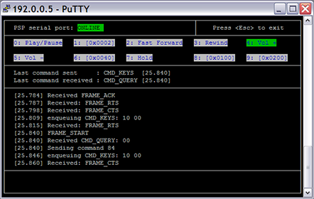
For more information, see http://nil.rpc1.org/psp/remote.html
It is therefore possible to use the PSP Remote Port as a serial port, which I guess is great news for all the developers out there (and also for any development of Linux on the PSP, as we can have easy access to a serial console).
Some quick notes about this:
1/ The 2.5V output can definitely be used to power an external device. As I found out, it has no problem powering the MAX3232 charge pump to supply +/-5V signals, and it doesn't appear to drain the battery more than usual
2/ As Marcus found out, pin #3 is indeed Tx (PSP -> Remote) and Pin #6 Rx (Remote -> PSP)
3/ As explained above, you need to have the audio jack plugged in for serial communications to occur. Without the audio jack, the serial port is not powered
4/ As I inadvertently found out (!), if you connect +2.5V with GND while the PSP is on standby mode, some kind of internal PSP reset occurs (you have to set the clock on next power on). Of course, I have to strongly warn anybody against using this as some kind of PSP reset method - you probably have as much chance to fry your PSP beyond repair in doing that: YOU HAVE BEEN WARNED!
5/ I did not find the unmapped Remote keys identified to have any effect at all. It looks like these extra codes are simply ignored. Of course, a proper analysis of the Remote driver should tell us more.
Now, some more information/speculation:
As I could see from the sceHP_Remote_Driver disassembly, the remote uses UART base address: BE500000. From looking at the other drivers, it would look like the PSP UARTs could be mapped as indicated below:
Now, as far as I understand, UART4 is used by the PSP modules for debug (printk anyone?), but we don't really know how to interface with it (you most likely have to open your PSP to access that specific port). On the other hand, we now have an easy interface to the Remote serial port, and we can definitely discard the Remote driver to replace it with something more useful.
What I have in mind would be to replace the UART4 driver with one using the UART3 (Remote UART) base, which should be failry easy to rewrite, to see what kind of information is actually being sent to UART4.
Of course this requires unloading the original UART4 driver and replacing it with our own (do we know how to do that?). Of course I am not talking about overwriting the actual PRX on the flash, but replacing a module when launching an application.
I guess experimenting with the Remote driver makes sense as it is a simple & non essential driver + having serial output on the PSP is very desireable.
Anybody has more information/ideas or knows what UART4 is used for?
For more information, see http://nil.rpc1.org/psp/remote.html
It is therefore possible to use the PSP Remote Port as a serial port, which I guess is great news for all the developers out there (and also for any development of Linux on the PSP, as we can have easy access to a serial console).
Some quick notes about this:
1/ The 2.5V output can definitely be used to power an external device. As I found out, it has no problem powering the MAX3232 charge pump to supply +/-5V signals, and it doesn't appear to drain the battery more than usual
2/ As Marcus found out, pin #3 is indeed Tx (PSP -> Remote) and Pin #6 Rx (Remote -> PSP)
3/ As explained above, you need to have the audio jack plugged in for serial communications to occur. Without the audio jack, the serial port is not powered
4/ As I inadvertently found out (!), if you connect +2.5V with GND while the PSP is on standby mode, some kind of internal PSP reset occurs (you have to set the clock on next power on). Of course, I have to strongly warn anybody against using this as some kind of PSP reset method - you probably have as much chance to fry your PSP beyond repair in doing that: YOU HAVE BEEN WARNED!
5/ I did not find the unmapped Remote keys identified to have any effect at all. It looks like these extra codes are simply ignored. Of course, a proper analysis of the Remote driver should tell us more.
Now, some more information/speculation:
As I could see from the sceHP_Remote_Driver disassembly, the remote uses UART base address: BE500000. From looking at the other drivers, it would look like the PSP UARTs could be mapped as indicated below:
Code: Select all
BE580000(?) UART1(?) Serial EPROM(?)
BE540000    UART2(?) IRDA
BE500000    UART3(?) Remote
BE4C0000 UART4 Uart4/kernel debug(?)What I have in mind would be to replace the UART4 driver with one using the UART3 (Remote UART) base, which should be failry easy to rewrite, to see what kind of information is actually being sent to UART4.
Of course this requires unloading the original UART4 driver and replacing it with our own (do we know how to do that?). Of course I am not talking about overwriting the actual PRX on the flash, but replacing a module when launching an application.
I guess experimenting with the Remote driver makes sense as it is a simple & non essential driver + having serial output on the PSP is very desireable.
Anybody has more information/ideas or knows what UART4 is used for?
This work interests me. I hope this will allow us to create other sorts of peripherals for the PSP. I am a first year electrical engineering major and designed a MIDI controller last semester. I have a question though... It was suspected at one point that there was some sort of audio in capability, perhaps somehow embedded in the remote input... is this still a possibility or can that be ruled out?? There is the little icon on the back of the PSP by the headphone/remote input that shows a headset, aparently with a microphone..
I think everybody knows about the planned microphone/headset extension by now.
If you look in one of my posts above, you'll see that there is a good chance that pins #1 and 4 are meant to be for the microphone input.
Of course the only way we'll know for sure is when the microphone addon becomes available.
As to creating peripherals, we first need to understand how to create a kernel driver for the PSP, which could take some time...
Good job.
This opens the door for a homebuilt keyboard.
Remember those keyboards that are used for the palm? They worked via the serial port.. Perhaps those can also be interfaced into the PSP and used with AIM/GAIM/other IM programs when those programs become availible.
It's most likely possible to figure out where UART4 is by looking at the board, but I'm not going to take my PSP apart anytime soon. :) Also I have a hunch that UART4 is probably accessible externally - so when they program in the firmware, they can also see any errors. I remember another thread with inside information about a controller used to program the PSP - that it was attached without opening up the PSP.
That might be difficult, because AFAIK, the I/O pins used by Sony on its CPUs have not been made public. There is a chance that, by analysing the paths of the Remote Port and IrDa ports, we can find the general region where the UARTs might be located on the CPU's pinout, but nothing forces Sony to group its UARTs around the same region, so this could be a wild shot.fireether wrote:It's most likely possible to figure out where UART4 is by looking at the board
A few of us have been wondering about that too, but I'm not so sure: Apart from the probable microphone input on the Remote port, do we know of any externally accessible pins on the PSP that have not been clearly identified? Plus I don't think Sony would want to make a debug UART that easily available, when they went great length to try to protect the product from prying eyes...Also I have a hunch that UART4 is probably accessible externally
The serial keyboard is a good idea, if such hardware is easily available. From what I have seen, it does not look like you could easily convert a PS/2 keyboard to be used with a serial port, because PS/2 needs a clock signal, so you would need an actual serial keyboard. Those could prove expensive/harder to find. Plus we will need a driver first, and that's another story...
Its not that hard to make. *grins*>NIL: wrote:The serial keyboard is a good idea, if such hardware is easily available. From what I have seen, it does not look like you could easily convert a PS/2 keyboard to be used with a serial port, because PS/2 needs a clock signal, so you would need an actual serial keyboard. Those could prove expensive/harder to find. Plus we will need a driver first, and that's another story...
According to the first reference, the PS/2 keyboard generates the clock rate. Its in the range of 10-16.7 kHz.
So if you want to make a PS2 keyboard interface.. Start with buying a cheap microcontroller. I would recommend one that has 5 IO lines, and an UART port.
From www.microchip.com, PIC16F688 has 12 I/O pins, 14 pins total, 20 MHZ max speed, and EUSART port. Plus the PIC16F688 can work down to 2.0 V. It also has an internal oscillator of 8 MHz so the external one doesnt have to be brought - lowering cost/size even more.
If I remember right, the PSP sources 2.5V, which can easily power the microchip. Then somebody could write code that allows the microchip to be an interface between the PSP and the PS/2 keyboard - all for maybe $5 or $10 in parts. This is especially true because a voltage level converter may not be needed between the PIC and the PSP, but may be needed between the PS/2 and the PIC.
As for driver.. Treat the UART 4 as a serial console except that nothing gets outputted except keyboard specific control stuff (such as turning on/off numlock, etc). So instead of accepting input from the onscreen keyboard, can accept from UART4. Or could be configured to accept from either.
To reduce parts - could get a PIC with a smaller pin count and an internal oscillator, and then code in the serial protocol. I.e. have two pins emulate by switching from 0v to 2.5v and so forth. They have some 8 pin microcontrollers which could be used for this.
An easier solution is to get a serial keyboard such as PALM's keyboard which costs maybe $50 to $100, and see if its compatible voltage-wise. There are also some other serial keyboards that can be used.
A driver base could be coded for those and put into the repos to ensure code compatibility (i.e. everybody uses same code for keyboards, so when new keyboards are added, it should work with all the products recompiled with new version of keyboard header files)
References:
http://www.computer-engineering.org/ps2protocol/
http://panda.cs.ndsu.nodak.edu/~achapwe ... board.html[/b]
I'm having a few difficulties building the cable, probably because I'm doing it my own way.
Here in Australia, getting a max3232 is a bit tough. So I opted for a max232, powered by the PC. I assume it's okay that I'm not drawing the 2.5V?
I also chose to reuse the Sony connector instead of carving up PCB. I suspect I don't need the audio jack, but it's there just in case.
But even with psp_remote (or just cat /dev/ttyS0) I can't see anything. I know the circuit works because I can use it with my netgear wgt634u (yet another broadcomm router). Has anyone else had difficulties making the cable? And solved them?
I guess an externally powered MAX232 should work too (the logic threshold on that IC is definitely lower than 2.5V).
The problem is that psp_remote uses the changes on the CTS signal (RS232) to find out whether the serial port is online or not. In the original montage, because the MAX chip is powered by the PSP, CTS (which is tied to V+) directly indicates the start of the window during which we need to tell the PSP that there is a device connected to it.
Remember, there is only a small timeframe after the PSP is powered on (or a jack is plugged in), during which the PSP will accept inbound data. Past that window (about 5 secs), the port goes offline and the PSP simply ignores any data that is being sent to it.
I guess you could try to feed the 2.5V power line (pin 5) to the T2In of your MAX232 and connect T2Out to CTS to achieve the same effect, but you will need a way to synchronise with the PSP, by knowing when the port goes online.
Oh, and you definitely won't see anything simply coming out from /dev/ttyS0 even with a proper montage. Until the handshake/init process has been completed, the PSP serial port does not speak unless spoken to.
Hope this helps.
-
AudioMonster
- Posts: 37
- Joined: Wed Sep 07, 2005 3:41 am
- Contact:
Has anyone else noticed that the remote controls PCB has the Microchip logo printed on it?mc wrote:Yes. The remote control contains a microcontroller of some sort (can't tell exactly which sort as it's covered in black plastic, as per tradition :), so one of the pins will definitely be a power feed to drive it. Don't know exactly which one though. I started investigating the remote control port, putting the results on http://mc.pp.se/psp/phones.xhtml, but I didn't have time to finish it at the time. If you want to help out with the measurements, you're welcome. Signal ground can be found on the normal headphone connector, to get a good reference point.
This leads me to believe that there would be a PIC under the epoxy marked as IC2... also strange that its labelled IC2... normally you would label the main IC as IC1

Hello
Hope this helps... Just to add to the mix.
The new PSP 2000 Remote for the Slim only get 1.85 volts... But looks like the same serial data scheme. But have not had the chance to pop it on a snoop to see the data.
Its very odd that the jack on the Slim and the remote handle 3 ring one being for the mike. But does not pass it on like that. The Slimm remote but feeds it { from a diagram some one else posted here } to one of the 12 pins... Very odd to wast a pin like that...
Grabed a cheep (.33 cents) Palm thumb keyboard for a m100/m105... Also a unfolding one for 5 dollars. Neither IR models. It just Serial out... Now if its a different baud rate will need to convert... Or can the PSP handle a rate beyond the normal one... I assume is 4800 8N1. Still need to get a tool chain going to build something..
Need Help.
Hi guys, I don't know if any of the original creators/contributors of this thread are still here since it's really old, but I am looking to make something and this info here is exactly what I need, that being said, I need some help and you guys obviously knowyour stuff so I was wonderingif you could help.
I am basically looking to build an IR remote control for the PSP, using the serial port, I have seen this done on many PSp speaker systems with remote controls.
Now, the IR part is not hte problem, infact it's a trivially simple problem, the bit I need help with is implementing the serial port communications of the hardwired remote into a PIC microcontroller.
If anyone is willing to help me with this project please give me a PM, any help or experience with this serial interface would be much appreciated.
Thanks.