
I have a question about building a serial cable for the PSP. I'm a little reluctant to ask this because I'm a total idiot when it comes to hardware, but here goes. I was looking for parts to build a PSP serial cable based on this: http://nil.rpc1.org/psp/remote.html
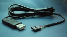
While looking for parts, I ran across this: http://www.sparkfun.com/commerce/produc ... cts_id=449
Would this thing work if I wired up the header to the PSP remote port?
Serial cable for dummies :-)

It seems to essentially run the same purpose as the max circuit, but I haven't looked into it too much so don't quote me :P
Shoot Pixels Not People!
Makeshift Development
Makeshift Development
This thing works great! I tested it with the SIO sample in the SDK. The greeting appeared on my terminal and the PSP responded as I typed. I cut off the controller from a PSP remote cable and wired it like so:
Vcc - yellow
Gnd - blue
Tx - gray
Rx - orange
To answer your next question: yes, I realize that I just wasted a Friday evening playing with serial cables.
Vcc - yellow
Gnd - blue
Tx - gray
Rx - orange
To answer your next question: yes, I realize that I just wasted a Friday evening playing with serial cables.
These could also be useful, but I've tested neither:

http://www.digitalnemesis.com/products/ ... fault.aspx
http://www.avitresearch.co.uk/usb_to_ttl.htm
http://www.digitalnemesis.com/products/ ... fault.aspx
http://www.avitresearch.co.uk/usb_to_ttl.htm
This one should also work (it's been mentioned somewhere else in this forum, but I thought it could be nice to collect the info in one place)
http://www.ftdichip.com/Products/Evalua ... MM232R.htm
dsn: Do you know what lowest voltage the sparkfun adapter can handle? Could not find any info on that at their page (I'm considering it for the 1.7V PS2 serial port)
http://www.ftdichip.com/Products/Evalua ... MM232R.htm
dsn: Do you know what lowest voltage the sparkfun adapter can handle? Could not find any info on that at their page (I'm considering it for the 1.7V PS2 serial port)
I don't know how low it can go, but I'm sure the guys at Spark Fun would be willing to answer any questions you have: [email protected]
From that ftdichip site:

http://www.ftdichip.com/Products/Evalua ... L-232R.htm
From the datasheet:
http://www.ftdichip.com/Products/Evalua ... L-232R.htm
From the datasheet:
All for $20USD. Snazzy.Integrated Level Converter on UART Interface and Control Signals - VCCIO pin supply can be from 1.8V to 5V. Connecting the VCCIO pin to 1.8V, 2.8V, or 3.3V allows the device to directly interface to 1.8V, 2.8V or 3.3V and other logic families without the need for external level converter I.C. devices.
5V / 3.3V / 2.8V / 1.8V Logic Interface - The FT232R provides true CMOS Drive Outputs and TTL level Inputs.
-
white rabbit
- Posts: 60
- Joined: Wed Jul 06, 2005 7:03 pm
I know that, of course I had the headphone plug in the jack if I was trying to
power anything from the blue and yellow wires.
I mean I have disconnected the headphone remote (circuit) from the other
end of the cable to reuse the cable, but the PSP only provides power on
those lines for a few seconds.
power anything from the blue and yellow wires.
I mean I have disconnected the headphone remote (circuit) from the other
end of the cable to reuse the cable, but the PSP only provides power on
those lines for a few seconds.
Excellent stuff DSN and thank you. You saved me alot of fiddling with components I dont have to get the max chips I do have working with it. Grabbed this and one of their serial cables for around 20 shipped to Canada to play with PSPlink (unfortunately the best I am able to send to the psp is at 9600, but receiving from the psp can go full speed).
-
kasikeeper
- Posts: 36
- Joined: Thu Nov 29, 2007 7:08 pm
Hi,
I was trying to build myself a serial cable with the suggested rs232 to ttl converter under
http://www.sparkfun.com/commerce/produc ... cts_id=449
I made sure the wiring is correct. When I connect the serial cable to my psp and the usb cable is also connected then the psp crashes. If usb is not connected then no crash occurs. I figured out that when the serial cable is inserted even touching USB GND with the USB GND plug crashes the PSP. What the hell can this be?
Ok, so I tried to connect with only the serial cable connected as i don't need the usb now anyway. I compiled the sio sample of the pspsdk and copied it into my fw1.5 folder. when i start the application the screen remains black and nothing happens if i try to connect with a terminal program... :-(
Has anyone seen this strange behavior or can you give advise?
Thanks,
Kai
I know that a real MAX232 circuit works fine,
although I don't use the LEDs.

Except you have to power it from the PC end of the serial port.
I can't see how the circuit you linked to works,
but I would assume it is essentially the same thing with the lower voltage version of the MAX232.
although I don't use the LEDs.
Except you have to power it from the PC end of the serial port.
I can't see how the circuit you linked to works,
but I would assume it is essentially the same thing with the lower voltage version of the MAX232.
If not actually, then potentially.
-
kasikeeper
- Posts: 36
- Joined: Thu Nov 29, 2007 7:08 pm
Thanks for the schematics, but I want to get my sparkfun converter up and running since I paid for it already.
I got the cable running - sort of. I compiled the sio sample given in the pspsdk and the module connects with my terminal program. However, I always only receive the value 1280 when I press a button. (i made sure the connection is at 4800baud 8n1 as stated in the readme)
When trying to send something back to the pc terminal from the sio sample (i added the string send command) i do not receive anything.
Can someone tell me what the normal behavior of the sio sample should be like. A screenshot would be nice.
-
kasikeeper
- Posts: 36
- Joined: Thu Nov 29, 2007 7:08 pm
Have you given the serial echo program in LUAplayer Lowser a go?
Not that I'd use it for any mre than testing, but I know that works
by echoing typed characters, and it does keep up with a Human typing on a keyboard.
I linked to the MAX232 circuit to comapre.
The circuit you have might be another Maxim IC with the same pinout.
Not that I'd use it for any mre than testing, but I know that works
by echoing typed characters, and it does keep up with a Human typing on a keyboard.
I linked to the MAX232 circuit to comapre.
The circuit you have might be another Maxim IC with the same pinout.
If not actually, then potentially.

Don't tink it matters in this case, but keep in mind that SIO sample in SDK does work or not depending on your luck, 'cause if it coexists with another expensive thread it looses data or detects garbage. Long ago I wrote a "SIO driver" to properly manage all kind of serial devices and a small serial console, too....if this whole software thing does not function, then it's an hardware issue!!
-
kasikeeper
- Posts: 36
- Joined: Thu Nov 29, 2007 7:08 pm
I checked the serial sample which comes with the Luaplayer distribution. Basically I see the same results. The displayed characters do not match the entered character code. E.g. a 305 is displayed when I press the A key. The returned values however are consistent throughout the tests and they are even equal between the sio sample and the lua sample.
One thing I noticed. The TX and RX LED's do not turn on when running the samples. Is that normal behavior as the board is only powered at 2.5V?
One thing I noticed. The TX and RX LED's do not turn on when running the samples. Is that normal behavior as the board is only powered at 2.5V?