Did anyone have the official part number of the Flash chip used in the PSP?
Its normal practice for a Flash chip to have a small recovery boot loader to load another firmware if the main one is corrupted. In fact I don't think I have ever come across one without this.
Steddy
BIOS Recovery Mode
Re: BIOS Recovery Mode
flash chips always come in empty. the manufacturer does not know what cpu will attach it so it is impossible to preprogram a firmware loader.
however some embedded devices have some sort of connector where you can attach a proprietary programmer. if that can be found in the psp, somebody would have to reverse engineer the 1.0 firmware in order to find out how the data has to be delivered in order to be written to the flash. then we could build such a programmer.
however some embedded devices have some sort of connector where you can attach a proprietary programmer. if that can be found in the psp, somebody would have to reverse engineer the 1.0 firmware in order to find out how the data has to be delivered in order to be written to the flash. then we could build such a programmer.
Normally if you have a "bad flash" and sent the psp back to a repair center they're using a so called "JTAG" interface.
This interface is a 5 wire connection cable, and with it you have full system access via the cpu to the ram/rom/flashes and you're able to re-program the flashes. (if you have also the right software *g* )
Desoldering the flashes at a repair center is today too expensive .. with an JTAG interface the flashes can be reprogged within a minute or two ... and if the console still won't work, they smash it away and send you a new one
Google "JTAG" may help 2 understand what's the deal ...
http://www.macraigor.com/ sell software that you can use for JTAGing nd here is a picture of a JTAG interface http://tailor-madecircuits.com/JTAG.jpg
-
PSP_killer
- Posts: 16
- Joined: Fri May 06, 2005 8:17 am

preprogrammed
Usually they are pre-programmed (or 'staged'). In very high volume manufacturing, the 30sec - 1min to program the flash kills the manufacturing
time so rather than do that, they provide an image to the flash manufacturer and they stage them for you so you can stick them down. That way
they also avoid needing JTAG on a production unit. Only developers need JTAG, all efforts usually are made to disable it in a production setting.
time so rather than do that, they provide an image to the flash manufacturer and they stage them for you so you can stick them down. That way
they also avoid needing JTAG on a production unit. Only developers need JTAG, all efforts usually are made to disable it in a production setting.
The Rockbox crew have done something similar...
... to re-flash dead iRiver mp3 players - the page is http://www.rockbox.org/twiki/bin/view/Main/IriverBDM. Also, Sony have NOT disabled re-flashing via jtag because they do it to repair dead PSPs. Maybe we should research the JTAG interface, and see if we can get any info about it. I believe there are free (as in speech and beer) tools to run the JTAG interface (there certainly are for the BDM interface used in Rockbox). George
Also..
... I read somewhere that Sony use the headphone remote connector to re-flash dead (ie, leaked firmware flashed) PSP's - could it be that the JTAG interface is exposed there? reading http://en.wikipedia.org/wiki/JTAG it looks like the JTAG interface is 4 pins - we have 6 on the remote (in addition to the audio) - im guessing these will be used for a future LCD remote as per minidisk players, so maybe they wouldnt have used 4 pins just for that... If we could find the jtag pins, it looks quite easy to build a parallel port -> jtag interface (just google for jtag).
I think the headphone socket is a good candidate.
I think i'll try and buy another 1.0 PSP then I can take it apart and have a look.
Also, in the image above, notice the two sets of large contact pads. Four pins in each set :) Are any of these located near the headphone socket?
The positions of these are:-
1. Just left of CXD2962GG
2. Bottom right of circuit board
There is no way that Sony would offer a service to reflash dead PSP's unless it was quick and cost effective to operate.
Steddy
ive worked on lots of devices, that have both debugging, and reprogramming jtag interfaces. never once did i encounter something that can be done without taking the machine appart, let alone something as silly as a headphone jack.
if a machine isnt running right how would sony know it was because the firmware needs a reflash? they still need to take it appart and look for other issues.
if a machine isnt running right how would sony know it was because the firmware needs a reflash? they still need to take it appart and look for other issues.
KiWi:
IC9001 does not look like a good canidate to me.
MIPS uses an interface called EJTAG... Which has a pin arrangement like this
* *
* *
* *
* *
* *
*
* *
I found this at http://www.mips.com/content/Documentati ... ?agree=yes
You just need to create an account and you can access the PDF.
I could be wrong... but it looks like the JTAG interface is somewhere else.
SCPH-50001/N
HD SCPH-20401 U
Eyetoy SLEH-00031
Network Adaptor SCPH-10281
Logitech Z680 via FIber w00t!
Sony Wega TV + USB Keyboard
http://staff.philau.edu/barberej/
HD SCPH-20401 U
Eyetoy SLEH-00031
Network Adaptor SCPH-10281
Logitech Z680 via FIber w00t!
Sony Wega TV + USB Keyboard
http://staff.philau.edu/barberej/
-
Famicom DS
- Posts: 18
- Joined: Fri May 13, 2005 5:46 am
Lol.... FIND is the operative word.
I only got mine 4 weeks ago from www.nuplayer.co.uk and that was 1.0 firmware. They may still have some left.
I only got mine 4 weeks ago from www.nuplayer.co.uk and that was 1.0 firmware. They may still have some left.
I encountered at least two devices with such capabilities. The GP32 for one, and my calculator. Both have an external connector.yackom wrote:ive worked on lots of devices, that have both debugging, and reprogramming jtag interfaces. never once did i encounter something that can be done without taking the machine appart, let alone something as silly as a headphone jack.
if a machine isnt running right how would sony know it was because the firmware needs a reflash? they still need to take it appart and look for other issues.
Live free, prosper, and under my rule.
Just to kill the idea of using the Remote Control connector for firmware programming, according to this page, this port is a simple RS-232 port @ 4800 bauds.
This looks promising at first, but even assuming that you can "somehow" increase the baudrate of this port to the maximum speed achievable on common UARTs (about 256,000 bauds), transferring a whole firmware using this mode would take way too long to be practical.
Moreover, nowhere in the MIPS R4000 specs is there any mention of the CPU being able to use an RS-232 interface for flashing/low level access purposes. Unless RS-232 is handled natively by the CPU, the Remote Control connector protocol has to be handled by the firmware itself (possibly through an additional UART chip). In this scenario, trying to use a firmware controlled RS-232 interface as failsafe mode for a firmware re-flash looks like a very stupid design decision indeed.
Finally, considering the number of potential hackers out there, allowing access to the firmware from this RS-232 interface would be a major blunder from Sony.
All in all, and as already pointed out by others, it seems extremely unlikely (to say the least) that the Remote Control connector can be of any use to access/reprogram the PSP firmware.
Oh, and I have to stress out that the RS-232 interface of the PSP uses 2.5V voltage while a PC one uses 12V so, don't even think about plugging the Remote Control PSP port directly into a PC COM: port => you'll most certainly fry something up on the PSP.
On the other hand, if you use a MAX233A RS-232 Driver/Receiver chip (or equivalent), serial communication between a PSP and a PC should be no problem (though limited to using the PC as the Remote Controller for now).
Now if we ever get Linux to run on the PSP (and get the kernel to control it), we will have found ourselves a killer serial console in this port! ;)
In fact, I wouldn't be surprised that Sony themselves use(d?) this serial interface as a console for PSP development, coz this is just too well suited a port for just a Remote...
Or it can be this... The RS232 port is just used for identification conformation, and the firmware is sent through the USB2 port. I have seen this sort of operation for sat recivers where you could wake a dead sat reciver by entering a special mode by the RS232 port and then send a predefiend password, after this you can get a help menu and be able to flash the reciver again though through the printerport allowing much higher flashing speeds.
But without the software or atleast being able to sniff the ports when a dead PSP is reflashed then this will be a very hard task...
However I do think there is a debug menu hidden somewhere maybe some effort in finding it would be good...
Best regards!
But without the software or atleast being able to sniff the ports when a dead PSP is reflashed then this will be a very hard task...
However I do think there is a debug menu hidden somewhere maybe some effort in finding it would be good...
Best regards!
-
Guest
Hardly. Read this link (to which the author of the above page heavily contributed) and then come back and talk.>NIL: wrote:Just to kill the idea of using the Remote Control connector for firmware programming, according to this page, this port is a simple RS-232 port @ 4800 bauds.
http://forums.ps2dev.org/viewtopic.php?t=986
While the jury is out, one is hardly in a position to say the idea is killed. That port may be 4800bps during normal PSP operation, but there is no reason it must stay that way.
Hi gorim.
Thanks for pointing that page out. I probably should have been more careful in my statement. There is always a possibility that a port can be used for anything.
My concern however is from a standard user's perspective.
The idea that was mentionned above was to re-flash the BIOS from a standard PC using only this Remote port.
If we assume that the firmware is 14 MB, knowing that the maximum speed of a 16550 (the standard PC UART) is 256Kb, the maximum speed we can achieve for serial transfer from PC -> PSP is 25 KB/s (that rate includes start and stop bits and no parity) => it would take about 10 minutes to do the full transfer.
Now, having to wait 10 minutes for a re-flash is something we can do, but I doubt the people at Sony want to have to wait that long. This leaves us with the following possibilities:
1/ Sony do use the Remote port for a re-flash but they probably don't use a standard serial protocol (or even a serial protocol at all) to increase the speed => this will make it problematic for the common man with to use a standard PC for a re-flash, which is our goal here.
2/ Sony do use the Remote port in standard RS-232 mode for a re-flash and allow a negotiable baudrate to be used, which basically equates to: "Sony loves us and is playing nice" ;) Worth investigating (we might be lucky!), but I wouldn't bet my life on it...
3/ Sony do use the Remote port in standard RS-232 mode during the re-flash process but not for the firmware transfer itself => the serial port is used as a low level console where you issue the transfer & flashing commands and the firmware itself is retreived through another interface.
This is commonly used in high end servers motherboards, but it requires to add logic for the additional port in the failsafe mode, which becomes expensive for a handheld device with its various constraints.
4/ Something completely different
Having read the post by roto, and especially the fact that there is mention of a dongle being plugged to that port for re-flash, I would go for 3/ with possibly the audio port itself being bypassed for high speed transfer (inconvenient, because an analog output only port would have to become a digital I/O port, but possible), especially since it would appear that the UMD emulation for development units are using the remote port (but whether they use the audio too is another story).
If the remote/audio is the only port that is used for development, I doubt the debug/console serial line is kicked out of the door when hi-speed mode transfers are used, so audio would be a good candidate indeed. I don't believe in USB2 because it is placed on the opposite side and because of the control logic it would require.
Now, the only thing that worries me in this wild speculation is the mention of the development cable providing power to the PSP too.
From what I have read, I see hardly any candidate in the remote control port's pins for input power, which would tend to indicate that this development cable is not plugged only to the remote port...
I guess a few of us here would die to get our hands on that supposed Remote port flashing dongle... :)
As identifying all the potential capabilities of the remote port is kind of becoming off-topic (firmware flashing being only one of them) and I have a few more questions, I think I'll post in the other thread.
But I would be greatly interested in hearing anybody's theories on how this remote port could be used for flashing.
What about sending some kB by a serial port for a first stage boot loader, which loads the system from memory stick or UMD, or even easier: Perhaps the restricted flash area contains a boot loader, which checks the memory stick first for a second stage boot program on boot.>NIL: wrote: But I would be greatly interested in hearing anybody's theories on how this remote port could be used for flashing.
I think you guys are on to something. On all of the embeded devices I've worked with there are usually 2 layers, the bootloader and the firmware/OS.
On some Windows CE devices, for example, you must first flash the bootloader via an rs-232 port. This process is usually slow, but the bootloader is tiny and it doesn't take long. Once that bootloader code is on there, CE and platform builder take over and can use ethernet, serial or usb to transfer the hefty firmware files (usually at high speeds).
The PSP likely operates the same way. So first step would be to find the TX and RX pins (and of course a ground) to access the bootloader. Has anyone messed around with trying to send data to the pins? Were you able to get a response at all? Did you try different baud rates? parity bits? handshaking? Even with garbage characters coming back at least there is a chance of some form of communication.
These are the things we should be looking in to, as it is likely that updating the firmware this way does not check encryption or your previous firmware before updating.
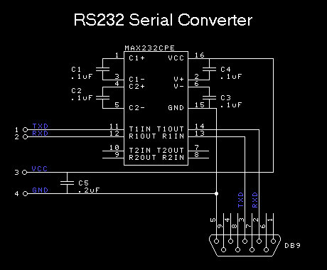
He is right, so you will definitely want to get some resistors before you attempt to do any of this.Oh, and I have to stress out that the RS-232 interface of the PSP uses 2.5V voltage while a PC one uses 12V so, don't even think about plugging the Remote Control PSP port directly into a PC COM: port => you'll most certainly fry something up on the PSP.
Typically, if you want serial communication between a PC and a PSP through the serial port, you'll need to build something like this. You can even fit such a montage into a standard DB9 - RJ45 serial connector if you use a MAX233ACPP, which is pretty sweet.
You can get free samples of these ICs from Dallas/Maxim if you're interested (these guys are cool so don't abuse their generosity!)
Now, I know such a montage works fine to convert 3.3V signals but I'm not sure about 2.5V (this voltage might be a little too low for the MAX chip). Unfortunately, I don't have a PSP to test that.
Read this one: http://forums.ps2dev.org/viewtopic.php?t=908&start=90
Its a different thread, but I talked about the serial port in that thread.
Basically I concluded that for it to be 2 minutes uploading and 1 minutes on testing, then its ~2.6 million baud rate. This is based on information somebody else supplied about how sony supposely loads firmware into the PSP on the production line.
Now, for serial port, 2.6 million baud is a little too high. However, I've seen SPI interfaces that use 2.5 MHz clock, and could probably approach this rate.
So it could be that the serial port is not a true serial port, but a SPI interface that emulates a bona-fide serial port.
On the other hand, the port may be an USB port thats able to "convert" to a serial port and back. Point is, until somebody knows where the serial port goes to (which chip, which pins) for sure, theres alot of speculations that can be made about it.
Plus, as I've said before, there can be a ROM bios in the PSP that will double as an emergency flash-loader. I.e. if the normal OS cannot start, it'll wait for a sequence from a source and then start the firmware load.. So far it looks like it'll wait for a sequence from the USB port or serial port. Others have said serial port, but will see.
aha! So there's a 3rd CPU (ARM9) on the PSP? This device is becoming a hacker's dream by the minute... ;)
The ARM9 has got to be the CPU that's responsible for serial I/O & firmware flashing, especially if the main CPUs run at 1.6V while the ARM only runs at 2.5.
Basically, Sony were easily able to pick a base ARM9 architecture and get a bunch of modules fitted onto it (that's SoC = System On Chip). ARM themselves can provide modules for audio, UART, Media Card, etc... (see here)
From a design perspective it also makes perfect sense to have the debug/recovery functions on an additional CPU like the ARM9, and I guess this is the CPU we gotta focus on if we want to understand the flashing process.
If I were to venture a guess, I'd say that the ARM9 handles:
- UART with debug/console, flashing interface and remote control
- Audio
- Additional high speed interface (possibly overlapping UART/audio)
- Bootstrapping & failsafe mode
- Firmware flashing
- UMD control
- 802.11
- MemoryStick?
- Possibly encryption
Of course, if we can retreive the ARM9 firmware, we'll have a much better idea on what can be achieved with the Remote Port...